StrobeCAM - Camera system for vibration analysis and vibration measurement
Videostroboscope with added valueThe StrobeCAM visualizes live and records vibrations and rotations in slow motion; for example on the electrodynamic shaker, on an engine test stand, at inaccessible locations or at miniature objects. The StrobeCAM is a user friendly and inexpensive alternate solution to high speed cameras and it adds a number of possibilities compared to a strobe light. |
    |
|
|
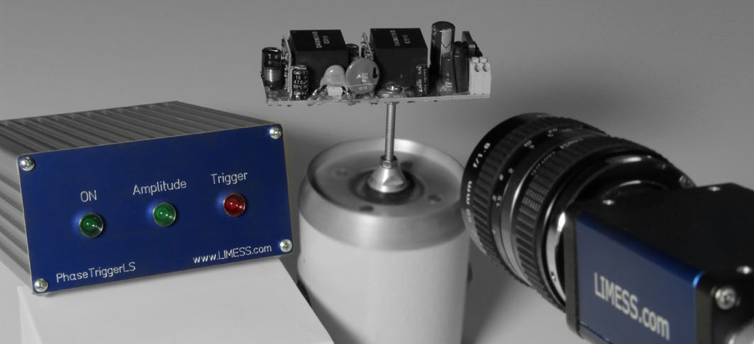
Innovative working principleThe StrobeCAM trigger unit controls precisely the camera's exposure moment related to the periodic process. The powerful LED illumination is constant in time. The object movement gets frozen due to the short camera exposure time which is comparable to the short duration of a strobe light pulse. The StrobeCAM trigger unit analyzes in realtime the input signal (COLA signal) and synchronizes the camera to it. The slow-motion visualization is user-friendly with an adjustable speed, e.g. 1 cycle/second and is independent of the excitation frequency. With this innovative principle, the component movement can also be clearly visualized over an entire frequency sweep. The standard system is equipped with an HD camera (2000x1200 pixels) and has a time resolution of 500kHz. Therefore the StrobeCAM gives a better quality slow motion image than an expensive high-speed camera. (A Typical high speed camera has only 512x56 pixels at 480kHz recording rate) |
Features
|
|
|
|
|
Technical Specifications
|
Frequency range: Cameras: Signal input: Delivery: |
1Hz to 60kHz 0,3 MPixel to 29 MPixel COLA signal from 0,5V amplitude Camera, lens, trigger unit, LED light, StrobeCAM software |
 |
Applications
- Vibration testing and vibration analysis
- Usage with elektrodynamic Shaker
- Visualisation, recording and documentation of object motion
- Measurement of resonance curve (frequency response)
- Measurement of resonance frequency
- Contactless component testing
- Transportation tests
- Environmental testing
- Zyclic Tests / rotating objects
- Fatigue testing (LCF/HCF/VHCF) in combination with Q400-DIC
Functional principle
Fast EventsThe visualisation and measurement of fast events is typically done with high speed cameras. Video StroboscopyThe term video stroboscopy origins from the diagnostic research at vocal cords. The motion of the voting lip is observed with a camera, endoscope and stroboscope illumination. |
StrobeCAMThe StrobeCAM is based on the precise synchonization of a digital camera to the periodic event. The illumination is done by temporal constant LED light. The synchronisierung of the digital camera requires a peridic input signal (COLA) from the test system (frequency generator, rotation encoder). Our microprocessor controlled trigger controller analyses the input signal and generates a precise phase synchronised trigger signal for the camera. The vibration frequency is allowed to be much higher than the free running camera recording frequency. |
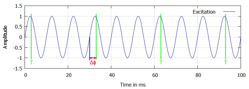
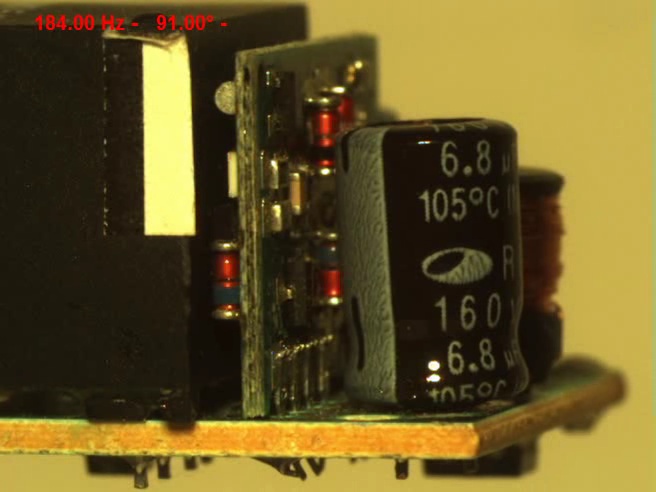
Still ImageExample: Assuming, that the camera can record images with max. 30Hz and the vibration frequeny is 100Hz. Then the trigger system will generate trigger signals every 3rd period of the input signal. The following diagrams show the time courses: At triggering with constant phase relation to the input signal the motion of the objects' vibration is freezed ("Still image")
|
 |
Phase SweepAt triggering with temporal varied phase (="phase sweep") the objects motion is shown in slow motion.The sweep frequency, e.g. 360° within 1 second defines the slow motion visualization speed.y 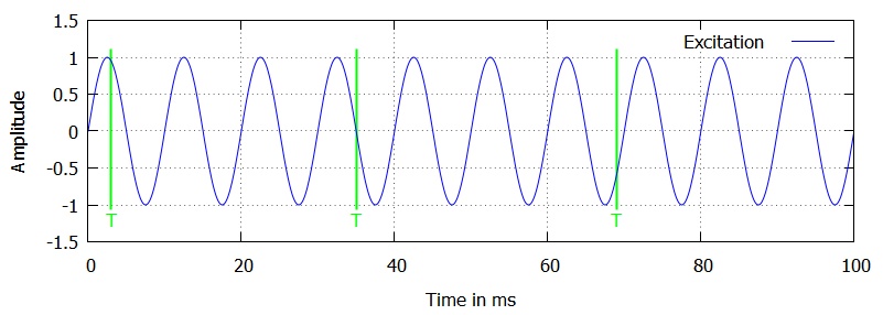 |
 |
Software
| Software | Functionality |
| StrobeCAM |
Camera control:
Video recording
Playback of recorded videos
|
Documents-Downloads
Leaflets:
Vibration measurement and vibration analysis in industry
Vibration measurement and analysis play an important role in many industries, from monitoring the condition of machines to ensuring the safety of structures and components. An overview of vibration measurement and analysis, including its history, its use in industry today, and future trends:
Quantification of vibration or movement
Vibration measurement quantifies the extent of vibrations present in a system. Vibration analysis is about determining the causes of these vibrations. Vibration measurement and vibration analysis are used together to diagnose weak points and problems and find solutions.
The first step in vibration measurement is usually to determine the source of the vibrations and thus the component to be examined. The most common sources of vibration are rotating or reciprocating machines such as pumps, compressors and fans. Other sources include electrical devices such as transformers and motors, as well as structures such as buildings and bridges, which are caused to vibrate externally, for example by the wind.
There are also vibration analysis methods that help to determine sources of vibration and get an overall overview of a vibrating system - for example using camera or laser systems.
Findings from a vibration analysis
Vibration can also be caused by imbalances in the load or structure, unbalanced forces, misalignment of components, loose parts, frictional forces, or aerodynamic effects. Once the source of the vibrations has been determined, the next step is to determine the frequency and amplitude of the vibrations. Frequency is measured in hertz (Hz) and is the number of cycles of oscillation per second. Amplitude is the maximum deflection of a vibrating object from equilibrium and is usually measured in millimeters (mm) or micrometers (µm). Other data such as temperature, material characteristics, humidity and switch-on time also play an important role in vibration analysis.
Measuring devices for vibration measurement
There are many different types of instruments for measuring vibration. These include accelerometers, which measure the acceleration of an object, displacement sensors, which measure the movement of an object, velocity sensors, which measure the speed of an object, and strain gauges, which measure the degree of deformation of a material.