MATERIAL TESTING application examples
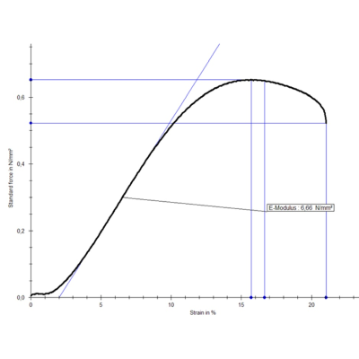
At material tests the force and strain ist measured during defined specimen loading (tension, compression, torsion, bending). From these measures the force-strain-curve and stress-strain-curve are determined and material parameters like Young's Modulus, poisson number, elongation at strain and more complex values are calculated.
Different camera systems can be used for the measurement:
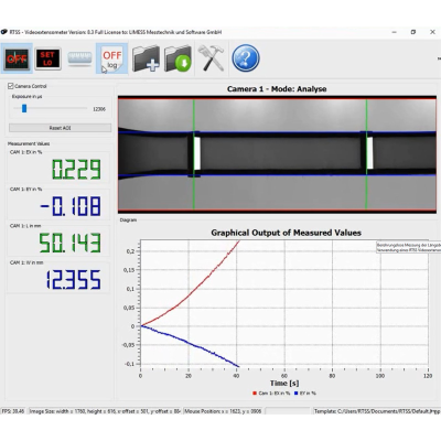
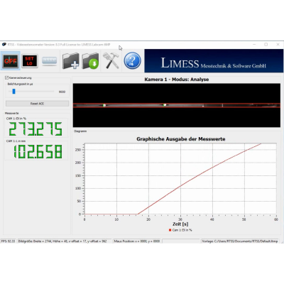
The RTSS-Videoextensometer is suited for standardized and automatic test procedures and works as a real time strain sensor..
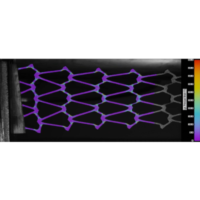
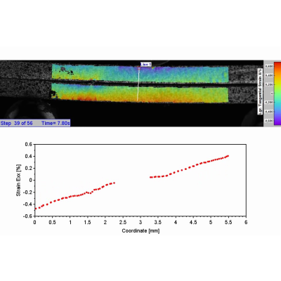
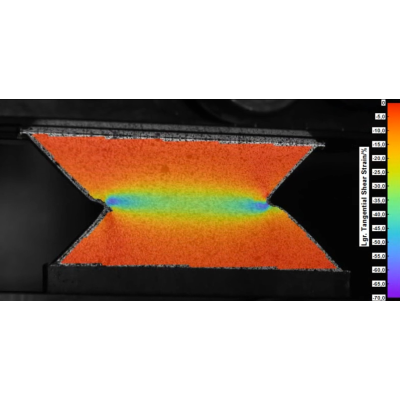
The Q400-Digital Image Correlation System measures spatially resolved strain values and the analysis is typicylly done in post processing because a large number of informations can be provided.
The importance of material testing
Material testing determines the physical and chemical properties of materials. Material testing can be used to determine the suitability of a material for its intended purpose. Material testing is essential for quality control in many industries, e.g. B. in the automotive, aerospace and construction industries.
Known material tests and material key figures
There are many different types of material testing, such as: Tensile tests, compression tests, hardness tests, fracture toughness tests and fatigue strength tests. Tensile testing is a type of mechanical testing that measures a material's ability to withstand tensile forces. Compression testing measures the ability of a material to withstand compressive forces. Hardness testing is a type of mechanical testing that measures a material's resistance to indentation. Fracture toughness testing is a type of mechanical testing that measures a material's ability to fracture under stress. Fatigue strength testing is a type of mechanical testing that measures the ability of a material to resist fatigue under repeated loading.
Particularly important material parameters: yield strength, modulus of elasticity, Poisson's ratio
Material testing can also be used to determine material parameters such as elastic modulus, Poisson's ratio and yield strength. The modulus of elasticity is a measure of the stiffness of a material. Poisson's ratio is a measure of the compressibility of a material. The yield strength is a measure of a material's resistance to plastic deformation.
Use cases of material testing
Material testing is essential for quality control in many industries, e.g. in the automotive industry, aerospace and construction. Material testing is used to ensure that materials meet the specifications required for their intended use. Materials testing is also used to investigate the cause of material failure. Accurate and reliable measurements are very important in both cases, as life-changing decisions sometimes depend on them.